


Analog Devices Inc. EV-DPS-PWRBDx Power Boards
Analog Devices EV-DPS-PWRBDx Power Boards are power attachments for the LT8740 device power supply (DPS) evaluation boards. Each power board has two output voltage rails: a positive output voltage (VPOS) and a negative output voltage (VNEG), with voltage levels depending on the variant. Each rail can deliver a 20A current. These Analog Devices EV-DPS-PWRBDx power boards utilize the LTC3871 PolyPhase® Controller. Each variant uses two LTC3871 ICs, one generating VPOS and the other generating VNEG. On the EV-DPS-PWRBD1Z and EV-DPS-PWRBD4Z variants, the LTC3871, which provides VPOS, is configured as a buck. For the EV-DPS-PWRBD5Z variant, the LTC3871, which generates VPOS, is configured as a boost. The LTC3871, which provides VNEG, is configured as an inverting buck/boost for all three variants. The inverting buck/boost receives input power from the VPOS for the EV-DPS-PWRBD1Z and EV-DPS-PWRBD4Z variants and VIN for the EV-DPS-PWRBD5Z variant.
Each rail can source or sink a roughly equal current since the LTC3871 has a symmetrical current limit. The current limit is set by the constant current loop of the LTC3871 and the resistor network tied to the SETCUR pin. When a load is placed from VPOS-to-GND or from GND-to-VNEG, the respective converter is sourcing power. The positive converter sinks power when an external voltage source greater than the regulated voltage is placed from VPOS-to-GND. Similarly, when an external voltage source is placed from GND-to-VNEG, which is greater than the absolute regulated value of VNEG, the negative converter also sinks power. The amount of current that flows into VPOS or out of VNEG when sinking power is set by the current limit of the external supply or the CC limit of the LTC3871, whichever is lower. When one rail sinks power and the other is not sourcing power, users must place a sufficient load across VIN to prevent the VIN from being boosted.
Features
- Fully supported power boards for LT8740 DPS evaluation boards
- IOUT(MAX) = 20A steady state, 22A peak for each rail
- Multiple test points allow easy access to all critical nodes and pins
- Synchronous rectification
- Source-sink feature procedure
- Programmable voltage and current outputs
- Digital PID control
- Current and voltage clamping
- SPI or 2-wire serial interface for control
Applications
- Automatic Test Equipment (ATE)
- Device power supply development
- Precision power control
Specifications
- Input voltage ranges
- 20V to 26V for EV-DPS-PWRBD1Z, 24V nominal
- 12V to 24V for EV-DPS-PWRBD4Z, 12V/24V nominal
- 20V to 26V for EV-DPS-PWRBD5Z, 24V nominal
- Output (reference-to-ground)
- ±17.5V for EV-DPS-PWRBD1Z
- +9.0V (VPOS) and -5.5V (VNEG) for EV-DPS-PWRBD4Z
- +30.0V (VPOS) and -5.0V (VNEG) for EV-DPS-PWRBD5Z
Required Equipment
- DC power source with at least 30V maximum and at least 30A output current rating
- Electronic Load capable of 800W, 0V to 60V
- Oscilloscope capable of a 500MHz bandwidth or above, 2-channel to 4-channel
- Precision digital multimeter (HP34401 or equivalent)
- Wires with ring connectors or alligator clips, use a wire gauge of at least 18AWG, with a wire length of at least 1ft for the input and output connections
x1Z Hardware Overview (Top)

x4Z Hardware Overview (Top)

x5Z Hardware Overview (Top)

Related Products
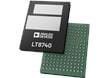
Analog Devices Inc. LT8740 Programmable Device Power Supply (DPS)
Programmable Device Power Supply offers high efficiency, integration, and performance.
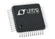
Analog Devices Inc. LTC3871 PolyPhase® Controllers
100V/30V bidirectional controllers ideal for 48V/12V automotive dual battery systems.