

 Türkiye


Electrifying the Future of eMobility
Commercial Vehicles: On the Road to Zero Emissions
By Alex Pluemer for Mouser Electronics
According to market research, electrified vehicles are overtaking the automotive industry, with EVs expected to account for half of all cars sold globally by 2035.1 Most EVs on the road are two- and four-door passenger vehicles. However, larger commercial and public transit vehicles are being electrified as charging and energy storage technology continues to evolve. Large commercial EVs like long-haul trucks, city and interstate buses, and delivery vans operate more often and for more extended continuous periods than passenger EVs and require larger batteries with more complex charging infrastructures. Off-road electrified vehicles used in agriculture or construction, such as tractors and bulldozers, also need more robust charging and storage capabilities than passenger vehicles. Traditional "heavy-duty" vehicles are responsible for a significantly higher percentage of greenhouse gas emissions per vehicle than internal combustion engine (ICE) passenger vehicles, as they have considerably more uptime and less efficient internal combustion engines. Integrating cutting-edge semiconductor technologies such as Littelfuse's silicon carbide (SiC) MOSFETs helps enhance the efficiency and performance of these larger vehicles.
Many U.S. states and countries worldwide are pushing industries to reduce carbon emissions and become less reliant on fossil fuels by encouraging the transition to electrified public and private transportation through regulations and incentivization programs.
In this chapter, we'll explore the challenges that come with electrifying larger vehicles and their subsequent wear and tear, advanced technologies (like SiC-MOSFETs) that are important in this transition, and the roles of local and national governments in facilitating this shift.

The Value Chain in Vehicle Electrification
The road to zero emissions begins with renewable energy sources like wind and solar power—storing and transferring that energy to vehicles efficiently is the key factor in powering EVs. The most direct energy storage and transfer method utilizes capacitors that boast higher power density than batteries and, therefore, can be charged (and discharged) at higher rates. Compared to batteries, capacitors aren't as adversely affected by repeated charging and discharging and, as a result, maintain optimal performance for much longer. Still, their lower energy density—the amount of energy they can store—means they're usually implemented in conjunction with batteries in EVs that require energy storage to provide greater range. Commercial EVs typically implement the same kind of lithium-ion (Li-ion) battery technology that passenger EVs do, although they're larger, by necessity, to meet the greater energy density demands. While currently available Li-ion batteries can withstand thousands of charge cycles, they degrade over time. Li-ion batteries are ubiquitous in EV designs, but the raw materials required to make them are in short supply globally, which has slowed down battery production in recent years. Alternatively, lithium iron phosphate (LiFePO4) batteries are increasingly used in electrified public buses that can be recharged overnight or on a down cycle.
Another renewable energy resource incorporated into commercial EVs is hydrogen electrolysis, which separates hydrogen and oxygen from water using electricity. Provided the source of the electricity is renewable, hydrogen electrolysis can create hydrogen in abundance while maintaining net-zero emissions. This process is performed by electrolyzers consisting of an anode and a cathode (like fuel cells) separated by an electrolyte. Electrolyzers can range in size from a small appliance to a large-scale power plant (Figure 1).

Some electrolyzers utilize liquid alkaline solutions of sodium or potassium hydroxide, while newer designs utilizing solid alkaline exchange membranes are in development. In contrast, other electrolyzers use plastics or ceramic materials as electrolytes, and each has its pros and cons. Solid oxide electrolyzers (ceramics) must operate at extremely high temperatures for optimal performance, typically in the 700 to 800°C range. Utilizing nuclear energy or other sources to create the necessary heat can decrease the amount of electricity solid oxide electrolyzers need to produce hydrogen. In comparison, polymer electrolyte membranes (plastics) and alkaline electrolyzers function at temperatures under 100°C.
Charging Solutions for Commercial EVs
Charging mechanisms for commercial EVs vary depending on the individual use case. Fleet vehicles like delivery trucks or public buses can be charged at their point of origin after they've completed their rounds for the day, with a single charge providing enough energy for an entire day's operation. Like charging a passenger EV at home overnight, depot charging a whole fleet can lower costs by taking advantage of lower energy prices at reduced demand. Constructing fleet charger stations modularly prevents the breakdown of a single charger from adversely affecting the rest of the system, and vehicles with excess stored battery energy that aren't in use can share with vehicles being charged for additional cost savings. Large depots also have the potential for expansive solar panel installations, and excess solar energy stored in stationary batteries can often be sold back to the grid to further offset costs.
Another way to keep fleet vehicles operational for longer periods, particularly public transport vehicles, is opportunity charging. Mechanisms called pantographs have been implemented in electrified trams and railways and can be used similarly to charge EVs intermittently during their hours of operation. Pantographs resemble highway weigh stations with frameworks that utilize electrical contacts that are lowered to the roof of the vehicle from above (Figure 2). Some pantographs work from the bottom up with the mechanism attached below the vehicle.

The energy transfer from a pantograph doesn't entail plugs or wires, and vehicles of various heights and shapes can be accommodated. Vehicles traveling along fixed routes can pick up an additional—usually partial—charge at planned intervals to optimize performance. Pantographs can be installed along the roadside, so they have a minimal impact on existing public infrastructure. Wireless inductive chargers, like cell phone charging on a larger scale, can also provide opportunity charging possibilities. However, energy is lost in the transfer and this method requires significant changes to existing infrastructure, making them a better fit for smaller vehicles in semi-public areas, such as airport baggage trolleys or golf carts.
Charging long-haul trucks and other material vehicles that travel greater distances and along undetermined routes requires chargers with greater energy and power density than passenger EV chargers. Chargers with 1500V and 3000A capacities can exceed rates of 4MW, making a 500kWh charge possible in less than 15 minutes. That amount of charge would provide approximately 300km of travel distance. Installing these higher-density charging stations along interstates and well-traveled routes will be integral to electrifying long-haul trucking in the future. As with passenger EVs, increasing the distance a single charge provides and reducing the time to complete that single charge will be essential to the widespread adoption of long-haul EVs.
Incorporating Advanced Semiconductor Technologies in EVs
As the electrification of larger commercial vehicles gains momentum, advanced semiconductor technologies become important in enhancing vehicle performance and efficiency. Littelfuse SiC-MOSFETs stand out in this field. These components, key in managing power more efficiently within the vehicle's electrical system, offer various advantages over traditional silicon-based components.
One of the benefits of SiC-MOSFETs is their higher efficiency, characterized by extremely low on-resistance. This means less power is lost through heat during operation, leading to an overall increase in efficiency. This feature is especially vital for large commercial vehicles, where managing large power loads is essential. Additionally, SiC-MOSFETs exhibit reduced heat dissipation. Their lower on-resistance and higher thermal conductivity make them more effective in distributing heat. This reduces the need for extensive cooling systems, making them more suitable for the demanding environments of commercial EVs.
SiC-MOSFETs also offer rapid switching capabilities. They can operate at higher switching frequencies (beyond 100kHz) compared to traditional silicon MOSFETs, which generally operate at around 20kHz. This enhanced switching capability significantly boosts the performance of power electronic systems, especially in critical areas like EV charging and energy storage technologies, where rapid operation and high efficiency are essential.
Incorporating SiC-MOSFETs into electric vehicles—especially those designated for long-haul trucks, buses, and other commercial uses—is a crucial step in overcoming the challenges of electrifying larger vehicles. By enabling more efficient power conversion, these advanced semiconductor technologies significantly contribute to the goal of zero emissions in the commercial vehicle sector.
Benefits and Incentives of Electrifying Commercial Vehicles
The electric commercial vehicle market was approximately 100 billion USD in 2022, and that number is expected to more than triple by 20302 by some estimates. State and federal governments around the world offer a variety of incentive programs to encourage electric vehicle adoption, including subsidizing EV purchases and the construction of charging infrastructure, and significant tax reductions or exemptions for EV-related expenditures. Coupled with government regulations designed to discourage the use of diesel fuel and reduce overall greenhouse gas emissions, the incentive to transition from ICE vehicles to electric has never been greater for individuals, corporations, and public institutions.
Transitioning from fossil fuels to renewable energy sources typically entails a significant expenditure at the outset, but results in meaningful cost savings over time, especially as the cost of oil continues to rise and solar power becomes more ubiquitous. The biggest remaining obstacle to widespread commercial and public EV adoption is developing charging infrastructures to service both fixed-route vehicles and long-haul transport vehicles.
The introduction of advanced semiconductor technologies, such as Littelfuse SiC-MOSFETs, is a pivotal advancement in this area. By enhancing the efficiency and performance of power electronic systems in EVs, these technologies help overcome the hurdles of electrifying larger vehicles. They not only contribute to more efficient power conversion but also support the demanding environments of commercial EVs, making the vision of zero emissions more achievable. And, with laws and regulations promoting and incentivizing charging infrastructure construction, global adoption of commercial EVs might come sooner than you think. 
1Goldman Sachs. "Electric vehicles are forecast to be half of global car sales by 2035." February 2023.https://www.goldmansachs.com/intelligence/pages/electric-vehicles-are-forecast-to-be-half-of-global-car-sales-by-2035.html.
2Mordor Intelligence. "Electric Commercial Vehicle Market Size & Share Analysis."https://www.mordorintelligence.com/industry-reports/electric-commercial-vehicle-market.
Electrifying Small Vehicles: Protection Is Key to Successful Electrification
By Alistair Winning for Mouser Electronics
In many areas of the world—especially in cities—small two- and three-wheeled passenger vehicles are often the most popular mode of transport. These vehicles, such as scooters and motorcycles, are ideal for urban transportation because they are inexpensive, small, and agile enough to navigate through heavy traffic; have low or no parking fees; and often contain onboard storage options. With traffic congestion in cities worldwide growing, small passenger vehicles are gaining popularity.
According to a study by Research and Markets, the global market for motorcycles, scooters, and mopeds was estimated at 48.7 million units in 2022.1 That number is predicted to increase to 76.8 million units by 2030. In comparison, ReportLinker expects the global market for EVs to reach 27.5 million units by 2027.2 The growth in EV sales is expected to drive electrification across other forms of transport, including two and three-wheel passenger vehicles. Electrification of the small passenger vehicle segment would go a long way to helping governments meet their green initiative targets while also improving air quality.
While the initial designs of EVs and small passenger electric vehicles may look similar to their counterparts with internal combustion engines, manufacturers of small passenger vehicles are starting to get more adventurous in their design. For example, Verge Motorcyles' TS electric motorcycle has its electric motor integrated into the rear tire, transferring the power from the motor directly to the road and providing more space for batteries. Taiwanese company Gogoro has pioneered another example of this divergence. The company has developed a system that allows users of electric scooters to remove the vehicle battery completely and plug it into a power wall to charge while taking a fully charged replacement from the wall.
(Figure 1). This quick and easy process minimizes the time the scooter is unavailable to drive.

In both EVs and small electric passenger vehicles, safety is paramount because of the large electrical currents involved in their designs. These currents can easily be high enough to endanger human life, destroy other components in the system, or cause a dangerous battery fire. Circuit protection solutions can be used to prevent these incidents. Sufficient protection of the electrical systems also ensures the vehicles are more reliable and provide the maximum range possible.
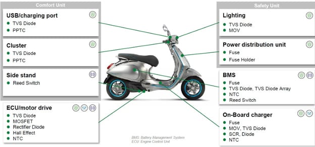
There are multiple sources of surges, voltage spikes, and overcurrent conditions, and circuits in small passenger vehicles need protection from them all. These electrical threats can cause varying amounts of damage, ranging from significant degradation to complete failure of the system. Fortunately, components have been designed to protect electric systems. Some of these components can protect from a single type of event, while others can protect from two or more. As such, they are often combined to provide complete protection for individual subsystems, between subsystems, and between the subsystem and the environment (Figure 2).
Electric small passenger vehicles can have a variety of operating voltages depending on the vehicle's requirements. For example, 72V or 48V batteries are often used for vehicles that require high speed and acceleration, whereas a vehicle focusing on efficiency and range will more likely use a smaller 36V battery. Other voltages in the vehicle will be kept as small as possible to drive key components like IC and microcontrollers, which operate on very low voltage.
Transient Voltage Suppression Diodes
As the name suggests, transient voltage suppression (TVS) diodes suppress transient voltages that could be introduced into the circuit from internal and external sources such as arcing, electrostatic discharge (ESD), and lightning. Unidirectional TVS diodes are designed to protect circuits from forward voltage surges, whereas bidirectional components can protect from both forward and reverse voltage surges.
TVS diodes operate by limiting voltage to their clamping level. To accomplish this, they are manufactured with a p-n junction with a large cross-sectional area, allowing large currents to pass to ground without damage to the component. They are very fast acting and easy to design into circuits. In the past, TVS diodes were a great choice for power circuits but a poor choice for communication lines because they had a relatively high capacitance that distorted high-frequency signals. Now, ultra-low-capacitance ESD diodes have been developed, which allows their use in the protection of communication lines.
Littelfuse offers several ranges of automotive-certified TVS diodes that are ideal for applications in small passenger vehicles. These devices feature operating thresholds from 5V to 650V and can handle power ratings from 400W to 7,000W in surface mount packages and 400W to 30,000W in axial lead format. TVS diodes are used to help the system comply with ISO 7637 and ISO 16750-defined surges, helping to ensure systems perform reliably for the expected lifetime. The different families tend to be based on transient wattage ratings to protect against transients of different severity.

One example of an ultra-low-capacitance ESD diode is the Littelfuse AQ3045-01ETG (Figure 3), which has been fabricated in a proprietary silicon avalanche technology that provides each I/O pin with a high level of protection from contact ESD strikes at ±30kV. The diodes can safely dissipate up to 3A of 8/20μs surge current with very low clamping voltages. They have an ultra-low capacitance of only 0.35pF, making them ideal for vehicular communication applications.

TVS and ESD diodes can be used in many other areas of small passenger vehicle design, including the instrument cluster, ECU/motor drive, battery management system, lighting, and the onboard charger.
Fuses
Much like fuses found in household applications, fuses in small passenger vehicles provide overcurrent protection. Fuses in automotive applications must comply with specific standards, such as AEC-Q200, which became the relevant standard when fuses were added to its scope in Revision E, published in March 2023. AEC-Q200 qualification guarantees that fuses are rugged and reliable enough to operate in the automotive environment.
Fuses for automotive applications are very similar to those used in domestic power systems and operate in the same way. When the current exceeds the fuse's threshold, its fusing element melts safely, protecting components downstream. As a blown fuse usually stops the system from functioning until it is replaced, fuses are used in the most critical areas and where dangers are greatest. In small passenger vehicles, fuses are most often used in the power distribution unit, battery management system, and onboard charger.
A complimentary technology to single-shot fuses is the resettable polymer positive temperature coefficient (PPTC) line, a resettable solution for applications with frequent overcurrent conditions or that require constant uptime. As an overcurrent event occurs, the PPTC solid state material heats up, which causes a change in the properties of its material composition. This property change raises the resistance of the device, thereby limiting the current. When the event is over, the device resets itself as it cools down, and its material reverts to its original structure. PPTCs are often found in the instrument cluster and the vehicle's USB-C charging port.

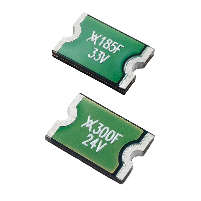
As a practical example, Littelfuse ASMDC PPTCs (Figure 4) have trip current values ranging from 0.6A to 6A at 25°C. ASMDC PPTCs come in a low-profile form factor and feature high DC and IHOLD ratings while meeting the most stringent requirements for automotive applications.
Summary
This article has given a general overview of some of the most popular components that can be used for circuit protection in small two- and three-wheel passenger vehicles. This list is not exhaustive; for example, NTC thermistors operate like PPTCs, only with a resistance that decreases with heat. These devices can be used to deal with inrush currents. Other standard components, such as diodes and MOSFETs, can also be used for circuit protection purposes. In combination, these solutions offer comprehensive protection that ensures small passenger electric vehicles can fulfill their full performance potential while operating safely.
1Research and Markets, Ltd. "Motorcycles, Scooters and Mopeds - Global Strategic Business Report." December 2023.https://www.researchandmarkets.com/reports/338746/motorcycles_scooters_and_mopeds_global.
2ReportLinker. "Global Electric Vehicles (EVS) Market to Reach 27.5 Million Units by 2027." Press release, October 10, 2022. https://www.globenewswire.com/news-release/2022/10/10/2530991/0/en/Global-Electric-Vehicles-EVs-Market-to-Reach-27-5-Million-Units-by-2027.html.
EV Circuit Protection and Components
Adam Kimmel for Mouser Electronics
As EVs become increasingly popular, with automakers projected to market more than half of their vehicle models as electric by 2030,1 the total cost to consumers will gradually come down. While EVs do not have a complex internal combustion engine (ICE), they have high-value components and systems that could be very expensive for consumers to replace.
Principally, the battery comprises 30 percent of the vehicle cost as of 2023, which is down from 50 percent in 2016 and is expected to fall to 20 percent around 2030.2 In addition to the battery, modern vehicles include critical safety, infotainment, and ADAS components that enhance the driving experience and safety profile. However, a major risk to these systems and components is electric shock, ranging from excessive voltage to transient surges and ground faults.
Higher voltage batteries and DC fast charging mean additional risks to the components, amplifying the need for electric vehicles to protect the battery and drivetrain circuitry. This chapter explores how circuit protection shields these electrical components in EVs, from batteries to subsystems.
Li-Ion Battery
Lithium-ion (Li-ion) batteries are integral to the functionality of electric vehicles for their high energy density that combats the risks inherent in managing high-voltage power systems.
Specs and Safety Risks
EV batteries operate around 400V to 500V and contain about 100 4.2V Li-ion battery cells. Meanwhile, next-gen battery packs are migrating to 650VDC–750VDC, and with higher-voltage packs comes better efficiencies during charging and on-the-road usage. Pack design and proprietary modules vary widely by manufacturer but generally deliver capacities ranging from 35 to 100kWh.3 With such significant kWh capacities, a short circuit becomes a considerable risk at voltage levels up to 500V. A short circuit in one cell can substantially raise the temperature, increasing the risk of a thermal event such as fire or thermal runaway.
Furthermore, batteries in EVs operate at peak efficiencies between 25°C and 35°C. When ambient temperatures exceed that range by a significant amount, the battery thermal management system (BTMS) provides supplemental heating or cooling to regulate the temperature. Failures or insufficient thermal management can negatively impact these added heat flows, shortening the life of the battery and increasing its risk of premature failure—and compromising safety in the process.
How to Protect the Battery
The best way to protect Li-ion batteries is through a multi-layered protection approach. There are system-level and module-level measures design engineers can take, starting with implementing properly sized current interruption devices. A fuse like the Littelfuse 881 AEC-Q200 High-Current Subminiature SMD can provide supplemental overcurrent protection in high-current circuits and is meant to be used at the module level. For cell-level, sense line protection, lower-amperage fuses like the 0437A series should be used. Adding transient voltage protection or suppressor diodes can also help protect the balancing circuits against harmful transient power spikes.
Additional battery protection measures include electrostatic discharge (ESD) protection, such as an ESD diode, where battery modules link together. The ESD diodes respond very quickly to the high-voltage ESD transient and clamp that spike to a very low voltage. It allows the sensitive circuitry to survive these potentially damaging events.
In addition, a whole-battery pack fuse protects the battery at the system level, guarding against current overloads and short circuit currents. Finally, adding a control and protect circuit with gate drivers can facilitate rapid switching of MOSFETs to protect the components from voltage transients.
Protect discrete battery modules
There are options to protect discrete battery modules as well. Adding low-voltage fuses, such as the 0437A series, will protect the sense lines from overcurrent due to component failures and short circuit conditions. For the battery distribution unit (BDU), engineers can employ high-current, high-voltage contactors to allow for the switching of various current loads.
Accessories
While the high-voltage battery creates significant risk potential, vehicle subsystems designed to enhance occupant experience, such as infotainment, driver assist, and vehicle autonomy, are also exposed to various electrical threats during their lifetime. These systems need proper circuit protection to ensure continuous function.
In-Vehicle Infotainment
EVs are elevating expectations for the occupant experience while driving. Infotainment features include audio and video controls, high-definition displays, compatibility with mobile phones, navigation, and over-the-air updates. Infotainment systems utilize low voltage circuits, and can be damaged when exposed to high-voltage voltage transients or electrostatic discharge. Engineers can apply overcurrent and overvoltage protection to these systems. A good example is the USB 3.0 port, whose specification includes protection for excessive voltage and current. Along with USB, HDMI outputs, BLUETOOTH®, GPS, and satellite radio RF outputs can incorporate ESD protection to avoid failure through electric shock.

Finally, the 12VDC power outlets can include resettable fuses, or polymeric positive temperature coefficient (PPTC) devices, to isolate equipment from power spikes.
Autonomous Driving Systems
Two primary autonomous systems are becoming prevalent in EVs: the autonomous driving system (ADS) and the radar subsystem. Though many equate autonomous vehicles (AVs) with fully autonomous driving (using the ADS), driver assistance features also support vehicle operations. These advanced driving assistance systems (ADAS) can handle challenging tasks like automated lane correction, parallel parking, and automatic braking.
The camera subsystem is integral to both ADS and ADAS. As drivers become more accustomed to having these systems at their disposal, protecting them from high-energy transients becomes increasingly necessary to ensure their availability. Similar to infotainment systems, including PPTC resettable fuses, or surface-mount ceramic chip fuses, can provide overcurrent protection. Furthermore, TVS diodes will help the system comply with the ISO 7637/16750 specifications to protect the system against transient voltages.
The vehicle's radar and lidar systems compliment the camera system to provide critical input from the vehicle's surroundings to the ADS/ADAS system. Protecting these key circuits, and the data they carry, is crucial to maintaining proper functioning.
Another circuit protection component to consider is the Schottky diode. It is installed in series with the power line, typically right at the power entry point. This component protects the circuit against reverse polarity conditions that occur when the power connection is reversed. It essentially blocks the reverse current flow that would damage many circuit components.

Finally, ESD protection like the Littelfuse AXGD Xtreme-Guard Automotive Suppressors provide ultra low-capacitance for the protection of high-speed lines like automotive Ethernet. This product offers less than 100fF of capacitance to ensure that it protects against electrostatic discharge without causing any signal degradation or distortion. Tested to the ISO 10605 ESD standard, it is robust enough to withstand 30kV events.
It is important to consider circuit protection early in the design cycle, especially for critical systems like ADS and ADAS. These components will provide overcurrent, short circuit, transient overvoltage, ESD and reverse polarity protection, and ensure the safe and reliable function of the critical subsystems.
Conclusion
As EVs continue to become more prevalent in society, maintaining consumer safety and protecting high-value components and systems becomes increasingly vital. The primary component of an EV, the Li-ion battery, operates at high voltage and can be damaged by transient and voltage surges, as well as exposure to overload and short circuit currents. Similarly, the ADS and ADAS systems are susceptible to the same electrical threats, so the inclusion of circuit protection components should be considered early in the design cycle.
Drivers and passengers are growing accustomed to, and dependent on, infotainment, ADS, ADAS, and related technologies in their vehicles. Remember that circuit protection solutions will deliver reliable performance and protect the vehicle components and subsystems to help deliver occupant safety, comfort, and convenience.
1Gartner. "Gartner Forecasts 15 Million Electric Cars Will Be Shipped in 2023." Press release, September 7, 2023.https://www.gartner.com/en/newsroom/press-releases/2023-09-07-gartner-forecasts-15-million-electric-cars-will-be-shipped-in-2023.
2Statista. "Projected battery costs as a large share of large battery electric vehicle costs from 2016 to 2030." October 24, 2023.https://www.statista.com/statistics/797638/battery-share-of-large-electric-vehicle-cost/.
3Power Electronic Tips. "Battery pack protection keeps EVs on the road." August 2, 2021.https://www.powerelectronictips.com/battery-pack-protection-keeps-evs-on-the-road-faq/.
Safe EV Charging via Circuit Protection
By Adam Kimmel for Mouser Electronics
The electric vehicle revolution has finally arrived
Through mega-drivers such as tightening emissions legislation, expanding charging infrastructure, and decreasing vehicle and electricity costs, electric vehicles (EVs) are projected to represent over 50 percent of vehicle models by 2030. This fraction equates to about 15 million vehicles by the end of 2023 and 18 million in 2024—an increase of nearly 20 percent.1
Consumers can look forward to EVs' ancillary benefits like infotainment, enhanced connectivity, driver assist features, and improved safety. However, barriers remain before the mass consumer base takes the plunge to electrify its driving experience, and two of the main barriers are charge time and safety.
Consumers expect the time to "refuel" their EVs to be similar to that of gas-powered cars while enjoying a comparable safety level. The following are currently available charging levels and their charge times:
- Level 1 (basic home): 120VAC (8–12 hours to charge fully depleted battery)
- Level 2 (home & public): 208–240VAC (4–6 hours)
- Level 3 (public & commercial): 380–600VAC (20–30 minutes to reach 80 percent charge)
While these charging levels expand drivers' charging options, the charge time and safety barriers are inversely related. As a result, elevating voltage to accelerate charge time creates a need for appropriate circuit protection for fast chargers. This circuit protection will mitigate safety risks while consumers adapt to interacting with higher-voltage equipment.
This article explores EV charging stations' power distribution units, risk factors, and circuit protection technology that enable high-voltage DC fast charging while protecting consumers.
Cabinet Unit Overview
The cabinet unit delivers power to critical EV loads. DC charging stations contain a network of fuses to safely regulate electricity flow. DC charger cabinet units contain six functional components:
- AC/DC power electronics
- DC/DC power electronics
- Mechanical systems
- User interface and network connectivity
- Auxiliary AC/DC power supply
- Electrical distribution system (e.g., fuses, ground-fault relay, transformer)
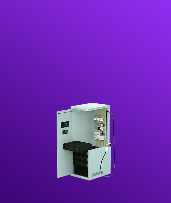
Figure 1 shows the DC charging station's PDU, its components, and failure risks for each.

The component systems allow the source of electricity to reach various systems like heating, cooling ventilation, and interior lighting. Power electronics convert and distribute the power in usable forms. At the same time, mechanical systems help control and monitor the physical conditions of components, such as the position detection of access doors and the temperature of the charging plug.
The remaining systems control the user interface, wireless connectivity, auxiliary power, and electrical distribution. Each of the six sub-systems requires circuit protection to withstand the risk factors that can compromise the user's safety.
EV Charger Risk Factors
The three primary risk factors to EV chargers occur through exposure of components to conditions outside their design point. These risks categories are excessive charge entering a pathway (e.g., overvoltage, transients, surges), charge following an unintended route (e.g., ground fault), or ambient conditions outside the specification values (e.g., environmental exposure).
Overvoltage, Transients, and Surges
EV chargers can endure excessive voltage or transients due to electrical faults or voltage fluctuations caused by lightning, switching, electrostatic discharge, or grid intermittency. Similarly, a sudden voltage increase when power returns following an interruption has the same effect on the system. These events can damage internal charging components, leading to arcing or overheating, reducing the equipment's lifespan, and increasing safety risk.
Ground Fault
A ground fault from the charger creates the risk of electric shock. As voltages increase and more consumers charge their vehicles, protecting against ground fault risk is critical.
Rugged Environment Exposure
Exposure to outdoor environments—such as extreme heat or cold, dust, humidity, high-salinity coastal air, or physical damage to the equipment—can add a variety of risk scenarios to the EV charger. Shortened component lifespan and material degradation create the opportunity for a safety hazard during fast-charging operation.
Charging Component Circuit Protection
Fortunately, highly engineered products like those used in Littelfuse Electric Vehicle DC Fast Charger Solutions incorporate layers of protection into the charging systems to de-risk these safety hazards as charging voltages continue to increase. The following sections present the protective features of the Littelfuse system grouped by the risks they address.
Overvoltage, Transients, and Surges
Excessive energy input to the charging system through overvoltage, transients, or surges is a common failure. But engineers have a variety of designs to guard against them:
- Surge protection devices such as SPD2 protect DC fast chargers against lighting surge. They are designed to withstand high-energy transients to prevent disruption, downtime, and degradation of the charging unit.
- Transient voltage suppressor (TVS) diodes provide surge protection from high-energy transients. They act as a voltage-clamping surge protector with low resistance and fast response time to absorb excess energy quickly.
- Varistors, like the Littelfuse UltraMOV 20mm series, are well-suited for high-voltage, high-current applications like DC fast charging. They can withstand higher temperatures than TVS diodes to "fail safely" in the event of thermal runaway due to excess current or voltage.
- Low-leakage current-switching diodes limit voltage fluctuation during a switching event.
- Schottky diodes mitigate reverse polarity and reduce turn-on voltage in the event of a power outage.
- Silicon carbide (SiC) and silicon MOSFET materials increase efficiency by raising the operating frequency and enabling fast switching of MOSFETs, reducing the inductor size. These shifts lessen the power draw and direct a higher fraction of source energy to the primary charging application.

Ground Fault
Ground fault relays sense low-magnitude ground faults, opening the circuit when the ground current sensor detects a critical current level.
Rugged Environment Exposure
- Engineers can design circuits as bridgeless power factor correction (PFCs) to minimize the number of semiconductors and increase the power supply's efficiency. SiC-MOSFET and diode combined with appropriate topology help to reach higher efficiency and minimizes ambient power loss and exposure, reducing loss and raising efficiency through lower charge draw amounts.
- Fast-responding high-voltage/high-current fuses protect against overcurrent, limiting excessive temperature exposure. System designers can also add reverse-flow protection diodes in the secondary rectifier for an added layer of safety.
- Temperature and proximity sensors monitor circuit temperatures to avoid overheating.
- Rugged-environment-rated materials protect against material degradation in harsh environments.
Figure 2 shows the EV charging station and protective measures for the respective component systems.
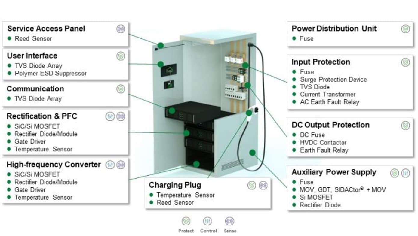
In Figure 2, TVS diodes protect the user interface, and SiC-MOSFET devices protect the power electronics and auxiliary power supply from overvoltage. Ground fault relays coupled with TVS diodes or other surge protection protect the electronic distribution center, and temperature and reed sensors protect mechanical components.
Conclusion
Adopting these circuit protection measures for EV fast charging complies with standards and protects users as the industry integrates electric vehicles into everyday life. A primary enabler for EVs is ensuring consumers can safely engage Level 3 DC fast chargers in public or commercial spaces. These charging stations will allow vehicle owners to experience a rapid "refill," like internal combustion engine cars. In addition, Level 3 charging will provide the user experience, performance, and sustainability gains only an electric vehicle can deliver.
1Gartner. "Gartner Forecasts 15 Million Electric Cars Will Be Shipped in 2023." Press release, September 7, 2023.https://www.gartner.com/en/newsroom/press-releases/2023-09-07-gartner-forecasts-15-million-electric-cars-will-be-shipped-in-2023.
Charging Ahead: eMobility Charging with Safety, Efficiency & Reliability

Thyristors for Megawatt EV Charging
By JJ DeLisle for Mouser Electronics
The rush to electrify industrial and commercial automotive systems is actively transforming current platforms, with a significant shift from internal combustion engine (ICE) technologies to electric vehicles (EVs). While the expansion of charging infrastructure remains a key hurdle in EV adoption, countries are aggressively pursuing incentives, subsidies, grants, and publicly funded projects to catalyze the build-out of EV charging stations. This push not only supports consumer EV uptake but also targets the larger energy and fuel demands of commercial and industrial vehicles. Electrification promises substantial emission reductions for municipalities, government operations, and industries involved in transportation, shipping, and logistics.
Scaling EV Charging Infrastructure to Support Commercial EVs
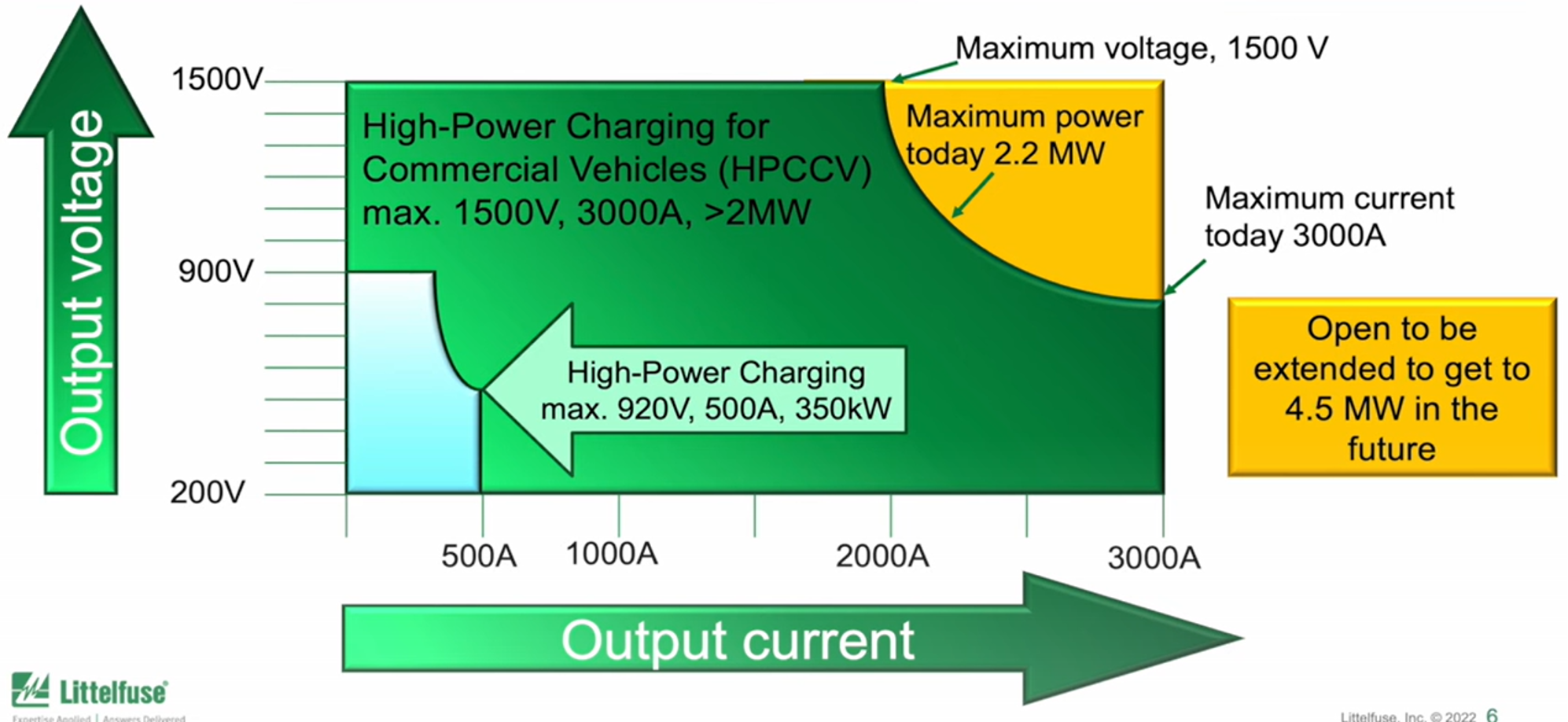
The long-standing barrier of consumer EV adoption was developing charging infrastructure, and this same barrier exists for commercial EVs, but with another higher-level challenge due to the need for much greater charging power rates. Currently, consumer EV charging stations are capped at 350kW charging rates, with a maximum of 920V and 500A. This is considered a low-voltage charging application, which enables reasonable charging times for consumer EVs, where the logistical challenges of charging are the burden of a user. Commercial EVs, on the other hand, have an entirely different set of logistical requirements where downtime needs to be limited to the small windows mandated by safety regulators for driver breaks. In the case of autonomous commercial vehicles, any downtime directly impacts the bottom line for commercial EV operators.
Hence, there is a clear demand for much higher charging speeds and infrastructure with commercial EVs. The current standards for High-Power Charging for Commercial Vehicles (HPCCV) allow for a maximum of 1500V to 3000A, making for a maximum charging power rate of 2.2MW (Figure 1). Though this is substantial, to reach charging rates that only require tens of minutes of downtime, it may be necessary to extend the HPCCV charging rates to 4.5MW. To reach these higher power levels, the fundamental approach to converting grid AC to DC voltage and current may need to be shifted to allow for rapidly and efficiently charging EVs.
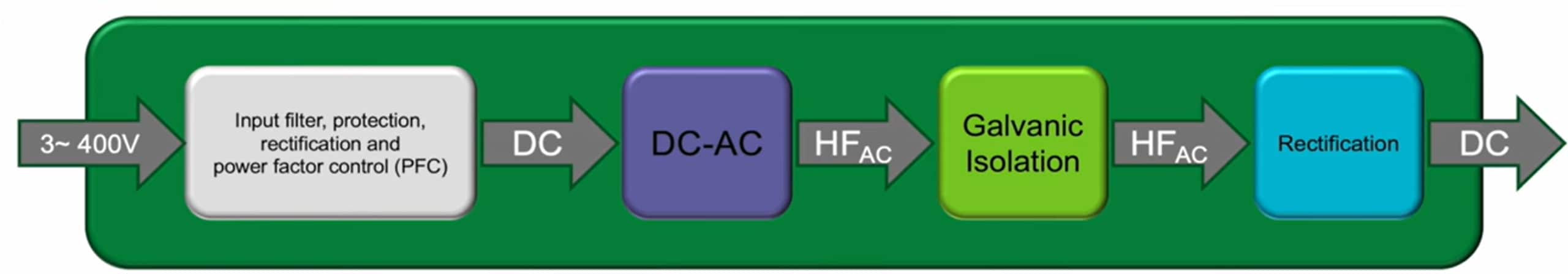
Today, the approach to building out DC fast chargers involves stacks of 60kW to 100kW units fed by three approximately 400V low-voltage AC inputs (Figure 2). This approach has worked well thus far, as stacking allows for some level of modularity and redundancy at the marginal cost of enhancing the interconnection effort and requiring redundant galvanic insulation per unit. Implementing a complete charging solution using this approach is typically done with a galvanic insulation LLC-stage and silicon-carbide metal oxide semiconductor field effect transistor (SiC-MOSFET) power transistors to convert the 3-phase AC input from the grid to adequate DC voltage levels for fast DC charging. This is often done using a Vienna rectifier for each of the 3-phase AC inputs and converting this rectified AC to high-frequency AC. At this stage, the galvanic insulation is often implemented before the high-frequency AC is rectified into smooth and stable DC.
Using Thyristors to Build HPCCV Infrastructure
The reported levels of efficiency reached by the latest SiC-MOSFETs are around 97 to 98 percent. Challenges associated with designing these units cause difficulties in achieving power outputs per unit greater than 60kW and an overall problem reaching the maximum voltages allowed by the CCS standards.
By taking a different approach that displaces the current method of galvanic insulation and changing the topology of the AC/DC conversion so that SiC-MOSFETs or other wide bandgap/high-power transistors aren't needed, it is possible to reach higher levels of conversion efficiency while also enhancing availability, reliability, and longevity for MW-level commercial EV chargers.
A way to achieve this is by using medium-voltage transformers to convert the 3-phase AC from the grid at 20kV to four roughly 690V medium voltage 3-phase AC lines. Each of these AC lines is then converted to DC between 700-1500V and 750A each and combined to form a 1500V and 3000A maximum, or 4.5MW charging system. This approach would shift the galvanic insulation from dedicated galvanic isolation transformers at each "unit" to highly efficient medium-voltage transformers, known to have efficiency levels above 99 percent. Moreover, the insulation voltage for these transformer types is often over 100kV, resulting in a solution that still allows redundancy with reduced material consumption and enhanced power density.

The last key to this puzzle is to design a circuit topology that can handle DC conversion at these higher voltage levels more efficiently than SiC-MOSFETs. As it turns out, there is already a technical solution to a similar challenge that has been used for decades. To perform industrial scale electrolysis reactions, thyristor bridges are used as part of the AC/DC conversion electronics that provide a very clean and stable DC voltage to electrolysis cells.
Thyristor technology is unsuitable for low-voltage EV charging at lower current thresholds of a few hundred amperes. At higher voltage thresholds above approximately 1000A, however, thyristor technology begins to demonstrate efficiencies that substantially exceed that of present SiC-MOSFET technology. Thyristors present relatively stable losses from a few hundred to roughly 1000 amperes. For example, theoretical estimates place the overall losses for a thyristor bridge used to convert AC to DC operating at 1000A to be the sum of 1000A × 1.148V (loss) plus two times 500A × 1.064V (loss). The sum is roughly 4.423kW, which is 0.2 percent of the total power used, for an overall efficiency of 99.8 percent. This exceeds the estimated efficiency of SiC-MOSFET technology by presenting 1/15 the loss.
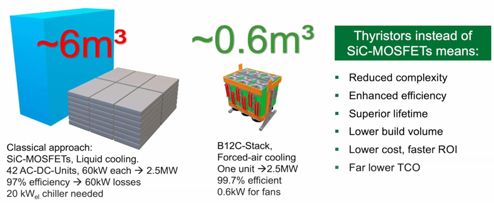
There are also other benefits of moving commercial EV charging from a low-voltage application to a medium-voltage application. Medium voltage transformers in this topology would be dedicated to commercial EV charging, with no other loads connected to the transformer. In this way, the entire commercial EV charger would be considered a medium voltage installation, and a separate set of grid codes then apply. In some countries, there are advantages to medium voltage grid codes. In addition, it is possible to design the transformer to deliver 500V output per B6-bridge, which allows for charging batteries up to 400V in a parallel connection and 920V in a series connection, meeting the needs of various battery voltage levels innately. Outside of direct electrical benefits, the much higher efficiency levels of the thyristor approach, intrinsic differences in how thyristors are manufactured, and the overall interconnect complexity results in a thyristor solution being around 1/10 the total volume of a comparable 2.5MW SiC-MOSFET solution (Figure 3). This is also partially due to the SiC-MOSFET charger unit requiring a chiller or much more substantial thermal management system than the thyristor charger.
Conclusion
Ultimately, a thyristor-based commercial EV charging system designed for MW charging can potentially exceed a SiC-MOSFET EV charger in efficiency, reduced complexity and size, superior lifetime, lower cost, and much lower total cost of ownership. Moreover, thyristor technology used similarly is tried and true technology with reliable supply chain and engineering resources. No new wheel needs to be invented to enable smaller and more efficient MW commercial EV charging that can ease the early pains of adoption for commercial EVs.